digging deeper on agc
Maintaining a constant power system frequency requires balancing total mechanical torque from turbines (prime movers) with opposing electrical torque from industry and household load demand. The responsibility for matching generation with load demand falls on system controllers.
In Australia system controllers are entities such as the Australian Energy Market Operator (AEMO) or the Power and Water Corporation (PWC) in the Northern Territory. System controllers balance generation with load demand by assigning a subset of generators in the network to act as regulating units.
Regulating units are generators that can be called upon to increase or decrease real power to the network. System operators use regulating units to adjust system frequency as required. The overarching control system that sends signals to the regulating units is called Automatic Generation Control (AGC).
Governors
The main mechanism for controlling a regulating unit is called a governor. This device consists of a valve on the entry to the steam inlet for the turbine. An basic block diagram of the setup of a governor mechanism to control turbine speed can be seen below.
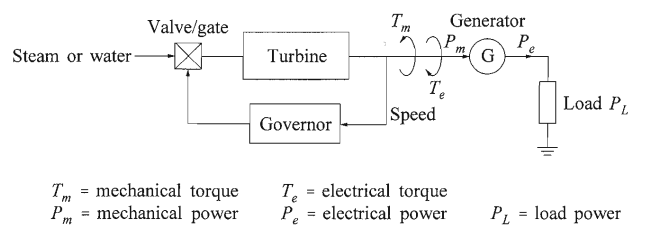
To get an operational understanding of a governor let’s consider a single generator supplying a local load, as depicted in the image above. The turbine drives the connected generator with some mechanical torque . This mechanical torque is opposed by an electrical torque, , from industry and household as they switch appliances on and off randomly. If the mechanical torque and electrical torque are balanced, then we’re golden and the system frequency will not change.
When a load change occurs (i.e. more load or less load) it is reflected instantly as a change in the electrical torque . This creates a torque imbalance between the mechanical and electrical torque resulting in angular acceleration. The angular acceleration changes the angular velocity of the rotating part of the generator.
At all times, the governor receives measurements (digital or analogue) of the angular velocity of the generator. If the governor detects a decrease in angular velocity, it will open a steam (or fuel) valve to speed the turbine back up. Conversely, if the governor detects an increase in the angular velocity, it will close the steam (or fuel) valve to slow the turbine down.
So the question you may have now is: how does the system controller send the correct signal to the governor to get the valve to open or close by the correct amount? Well originally there a basic proportional (P) feedback control loop used to do most of the work; however, this wasn’t perfect and the P controlled system would often settle with some permanent offset from the desired frequency. To counter this, some poor bloke would have to monitor the system and then run around making adjustments to the generators to ensure that system frequency was maintained.
One of the main innovations to overcome the limitations of the P controlled system, was the introduction of an integral feedback loop. This is more commonly known as a proportional integral (PI) feedback loop controller. The introduction of this additional feedback loop was sufficient to maintain power system frequency at the desired level under the tenuous assumption that the power system could be represented by a series of first order linear systems.
In the literature, the proportional feedback loop is referred to as the primary control, and the integral feedback loop is referred to as the the secondary control.