modelling the governor
When looking at a single area power system, there are three main components that the literature has a tendency to focus on:
- Governor: used for controlling the angular velocity (and frequency) of the system;
- Turbine: this is the steam turbine which provides the mechanical torque to drive the generator; and
- Generator load: describes the electrical power that is produced and the electrical torque from connected loads.
The derivations are a bit involved, but worth understanding. This post will cover the basics of how the literature goes about modelling a governor for a steam turbine. Other governor models can be more involved as the mechanical complexity of the turbine increases.
The analysis below will draw heavily from Kothari’s awesome book: Modern Power Systems Analysis.
governor model
The most important part of a speed governor are the two large masses (the pair of balls) which spin around a central axis. These masses are mechanically coupled to the the turbine drive shaft, so their angular velocity is a function of the turbine speed. Elgerd’s Electric Energy System Theory: An Introduction provides a really great schematic representation of the governing system for a steam turbine, shown in Figure 1. This schematic is used to derive the plant model for the governor.
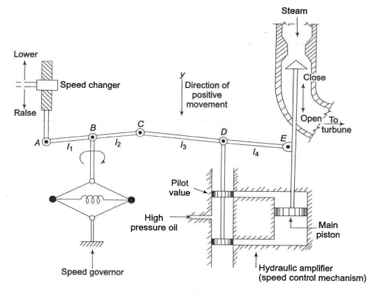
If we let on the in the schematic be moved downward a little bit, , the turbine power output will change by a directly proportional amount. Letting be the power increase, this can be expressed as:
An increase in will cause the pilot valve to move up, and high pressure oil will flow onto the top of the main piston forcing it downwards. As the steam valve opens, more steam will drive the turbine faster and causing the flyball governor to lower point . Mathematically, the movement of can be expressed as the result of two separate inputs:
-
Assuming that is small, using similar triangles, it can be written that:
-
Given a frequency increase point will move downward so, assuming is fixed, then using similar triangles it is clear that:
Letting , , and using equation (1), the total movement in point can be expressed as:
A similar analysis, considering movement of point and , can be undertaken to mathematically express the movement of point . The analysis also makes use of similar triangles and results in the expression:
Letting and , this can be re-expressed as:
When there is some movement, , of point the ports of the pilot valve will open and high pressure oil will plow onto the cylinder causing some movement . If point moves up, high pressure oil will move point down, and conversely if point moves down, high pressure oil will move point upwards. To simplify the dynamics of this scenario, the following assumptions are made:
- Inertial reaction forces of the main piston and steam valve are negligible compared to the forces exerted on the piston by high pressure oil
- Due to the first assumption, the rate of oil admitted to to the cylinder is proportional to the port opening .
The volume of oil admitted to the cylinder is thus proportional to the time integral of . Dividing the oil volume by the cross-sectional area of the piston:
Taking the Laplace transform of equations (2), (3), and (4) gives the following:
Algebraically manipulating (5), (6), and (7) eliminates and and results in the following equation:
Equation (8) can be re-expressed as:
where
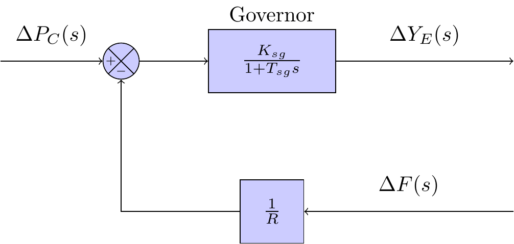
Equation (9) is the model of the governor in the frequency domain. The parameter is referred to as the speed regulation of the governor; the parameter is referred to as the gain of the speed governor; and the parameter is referred to as the time constant of the speed governor.
The complete block diagram of governor model can be seen in Figure 2 below.