modelling the turbine
When looking at a single area power system, there are three main components that the literature has a tendency to focus on:
- Governor: used for controlling the angular velocity (and frequency) of the system;
- Turbine: this is the steam turbine which provides the mechanical torque to drive the generator; and
- Generator load: describes the electrical power that is produced and the electrical torque from connected loads.
The derivations are a bit involved, but worth understanding. This post will cover the basics of how the literature goes about modelling a the generator load of a power system.
The turbine analysis below will draw heavily from Kundur’s elegant book: Power System Stability and Control.
turbine model
Consider a fossil-fuelled single reheat tandem-compound turbine. For the purposes of developing a model, a basic configuration of components can be seen in Figure 1. Steam enters the high pressure (HP) section through the control valve and the inlet piping. The housing for the control valves is called the steam chest. The HP exhaust steam is passed through the re-heater. The reheat steam flows into the IP turbine section through the reheat intercept valve (IV) and the inlet piping. The crossover piping provides a path for the steam from IP section exhaust to the low pressure (LP) inlet.
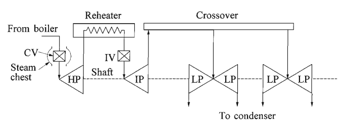
The control valve position, , modulates the steam flow through the turbine for load/frequency control during normal operation. The response of steam flow to a change in control valve opening exhibits a time constant due to the charging time of the steam chest and the inlet piping to the HP section. The intercept valve is normally used for rapid control of the turbine in the event of an overspeed, and won’t be considered in this analysis. The reheater holds a substantial amount of steam and has a time constant . The steam flow into the LP sections experiences an additional time constant associated with the crossover piping. Figure 2 shows the block diagram representation of the tandem compound reheat turbine.
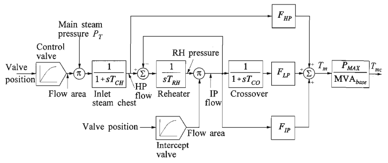
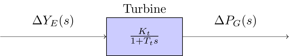
To simplify the model shown in Figure 2, it is assumed that is negligible in comparison to . Moreover, the remaining two time constants, and , have been combined into a single time constant . Hence, the power output of the turbine, , can be linked to the valve position, , in the frequency domain with the following expression:
Equation (1) is the simplified model of the turbine in the frequency domain. The parameter is referred to as the gain of the turbine; and the parameter is referred to as the time constant of the turbine.
The block diagram showing this representation can be seen in Figure 3 below.