modelling the generator load
When looking at a single area power system, there are three main components that the literature has a tendency to focus on:
- Governor: used for controlling the angular velocity (and frequency) of the system;
- Turbine: this is the steam turbine which provides the mechanical torque to drive the generator; and
- Generator load: describes the electrical power that is produced and the electrical torque from connected loads.
The derivations are a bit involved, but worth understanding. This post will cover the basics of how the literature goes about modelling a the generator load of a power system.
The analysis below will draw heavily from Kothari’s awesome book: Modern Power Systems Analysis.
generator load model
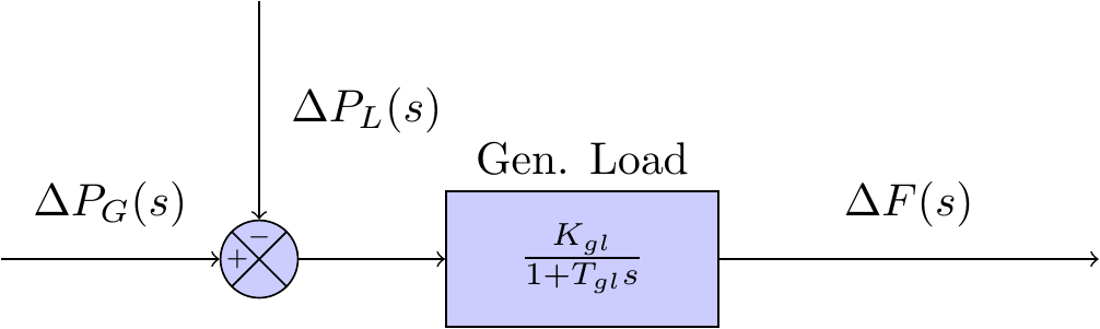
If the turbine output is in some steady state, and the power system experiences some perturbation, then let the incremental power from the turbine be . Noting that the main perturbation experienced by a power system is the change in load demand, , the incremental input to the generator-load system is given by .
The increment in power input to the system is accounted for in two ways:
-
Rate of increase of stored kinetic energy in the generator rotor. At scheduled frequency , the stored energy is:
where is the kilowatt rating of the turbo-generator and is defined as it’s inertial constant. Given that the kinetic energy is proportional to the square of the speed (frequency), the kinetic energy at a frequency of can be written as:
The rate of change of kinetic energy is therefore:
-
Given that motors make up a reasonable percentage of the load demand it must be considered that the motor load changes as the frequency changes. The rate of change of load with respect to frequency, , can be considered constant for small changes in frequency and can be expressed as:
where can be empirically determined, and is dependent on the proportion of motors that comprise the load demand. Note that is is positive, then the the load is predominantly comprised of motors.
Using equations (1) and (2), the power balance equation for the incremental input to the generator-load system can be written as:
Dividing throughout by yields the following:
Taking the Laplace transform of equation (3) and rearranging, we get the following expression:
Equation (4) can re-expressed as:
where
Equation (5) is the model of the generator-load in the frequency domain. The parameter is referred to as the gain of the generator load; and the parameter is referred to as the time constant of the generator load.
The complete block diagram of governor model can be seen in Figure 2 below.