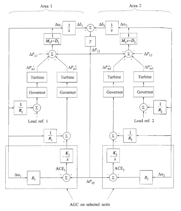
two area p control in the frequency domain
| Description | Parameter | Value |
|---|---|---|
| Speed governor gain | \(K_{sg1}, K_{sg2}\) | 1.00 |
| Speed governor time constant | \(T_{sg1}, T_{sg2}\) | 0.20 |
| Turbine gain | \(K_{t1}, K_{t2}\) | 1.00 |
| Turbine time constant | \(T_{t1}, T_{t2}\) | 0.50 |
| Generator load gain | \(K_{gl1}, K_{gl2}\) | 1.25 |
| Generator load time constant | \(T_{gl1}, T_{gl2}\) | 12.5 |
| Speed regulation of the governor | \(R_1, R_2\) | 0.05 |
| Load demand change | \(\Delta P_{L1}, \Delta P_{L2}\) | 0.02 |
| Speed changer | \(\Delta P_{C1}, \Delta P_{C2}\) | 0.00 |


comments powered by Disqus