two area power system modelling
We have seen models for a single area power system; however, this is an over simplification of reality. Time to up the ante on model complexity. Yeehaw!
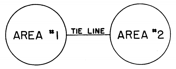
This post is going to consider two single area power systems connected by a tie line. A tie line can just be thought of as a transmission line for the purposes of this model, but could also be a distribution network. The model comprised of two single area power systems is conveniently known as a two area power system model.
You will be dazzled by the high level overview of the concept shown in Figure 1.
Before I dive into the modelling, I just wanted to quickly talk about the definition of a power area in case the reader is not familiar with this concept. Typically, a power system is comprised of many different generators and many different loads. These generators and loads can put into groups known as power areas. Essentially power areas are just a convenient way to aggregate lots of generators into a single generator, and lots of loads in to a single load. This simiplificaiton makes modelling easier.
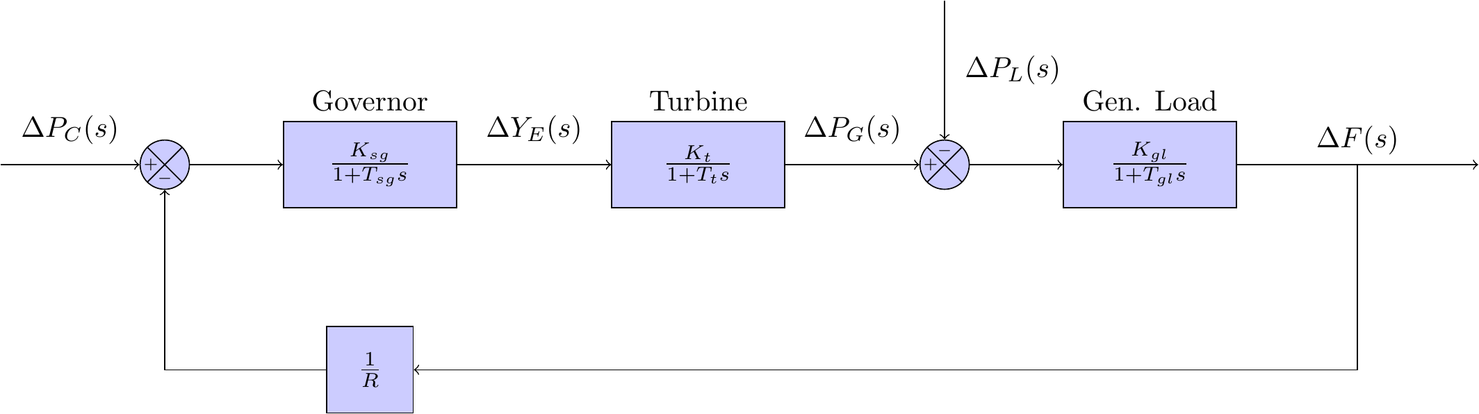
Now the power systems in each of the control areas in Figure 1 are very similar to the single area model shown in Figure 2. In fact, we don’t have to change our governor, or turbine models. We do, however, still have make some changes — these are as follows:
- model the interaction of the two power systems over the tie line; and
- re-analyse our generator-load demand model.
To kick off our thinking, let’s focus on the tie line.
The tie line allows for the flow of power from area 1 to area 2, and vice versa. For the convenience of this derivation, let any symbol with a subscript of 1 refer to power area 1 and those with a subscript 2 refer to power area 2. Now, letting the power angles of the area 1 generator and the area 2 generator be and , respectively, we can write an expression for the power transported out of area 1 as:
Using incremental changes in , we can determine an incremental change in the tie line power with a bit of trig magic and some old fashion Taylor series hijinks — this is expressed as:
Note that is the synchronising coefficient, and is mathematically expressed as:
Now, incremental power angles are integrals of incremental frequencies (because frequency is basically the same as angular velocity). This allows us to re-express equation (1) as:
The variables and are incremental frequency changes of areas 1 and 2, respectively.
Power can flow both ways over the tie line - the ideas governing the flow from area 2 to area 1 are symmetrical to those presented above. Hence, we can write:
Note that the synchronising coefficient can be expressed in terms of , hence, we can write that:
Okay, so we have some useful results derived for expressing tie line power flow. Specifically, we have tie line power flow from area 1 to area 2, and from area 2 to area 1. Now we need to (!PUN ALERT!) tie everything together. To do this, we need to take the inverse Laplace transform of equation (2) which gives us:
And then we need to take the inverse Laplace transform of equation (3), which gives us:
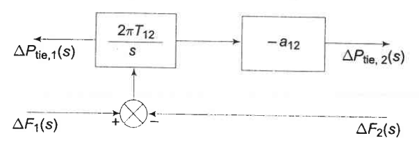
Equation (4) and (5) provide guidance on how to structure the block equation for the tie line. Note that the input for both (4) and (5) is , and the transfer functions for (4) and (5) differ by a factor of . The tie line block diagram is shown in Figure 3.
Okay. Phew. That has been a lot so far…
Sadly, we aren’t finished yet — this is the blog post that never ends.
The last thing we need to understand is how the output from the tie line feeds back into areas 1 and 2. To achieve this, we need to re-consider analysis that was undertaken all the way back here — if you really want to understand this next part, you should go and read that now.
It’s okay, I’ll wait. I can busy myself with this.
Up to date now?
Okay, good.
Essentially, this analysis used a power balance equation for the generator-load system. It posited that the incremental power input to the generator load system was given by and that this difference was made up from the rate of increase of stored kinetic energy in the generator rotor, and the additional power drawn by frequency dependent loads such as motors. In the presence of a second power area, this power difference could also come from the power given (or taken) over the tie line.
Using this idea, we see that the incremental power balance equation for area 1 can be written as:
A couple of parameters got introduced in equation (6). These include: the generator inertia, ; and the static rate of change in the load demand with respect to frequency due to motors, .
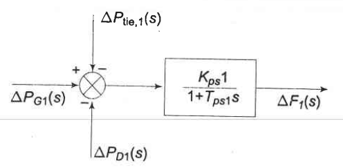
Taking the Laplace transform of equation (6) and rearranging, we get:
where
Equation (7) shows that the only thing to really change is that the generator-load system now has an input from the tie line. Note that power could flow either way depending on the scheduled contract for provision of power between area 1 and area 2. Figure 3 shows the generator-load block diagram with the additional tie line input.
The same analysis can be performed for power area 2, which results in the following expression:
where
A block diagram showing the new tie line input to generator-load system for power area 2 can be seen in Figure 5.
That’s it! We’re done. With the block diagrams shown in Figures 3, 4, and 5, along with the governor and turbine models, we can complete the model for a two area power system. Yay!
We obviously haven’t undertaken the modelling for the control system, but that can wait till next post given that this is already the blog equivalent of Tolstoy’s War and Peace.