primary control
The models developed for the governor, turbine, and generator load can be joined to make a complete model of a single governor control generator, powering a load.
The full block diagram can be seen in Figure 1.
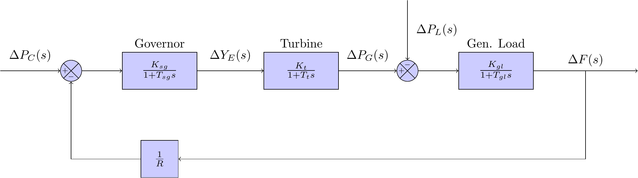
The block diagram above shows a single feedback loop to the governor - this loop is a proportional feedback controller, and is referred to in the literature as the primary control loop. There are two separate inputs to this model above:
- - the change in the speed changer setting; and
- - the change in the load demand.
Assuming that is zero, analysis can be undertaken to help understand the dynamic response of the system for a step change in the load demand. The literature refers to this scenario as free governor operation.
The step change for the load demand, in the frequency domain, can be expressed as:
Algebraic analysis of the block diagram in Figure 1 will yield a transfer function for the system, written as:
Using equation (1) and equation (2) the response to the step input can be written as:
Analysis of as is a well known approach for determining the steady state of the system, that is:
The result shown in (5) highlights that proportional control (or primary control) will arrest frequency deviations from a load demand perturbation; however, the controller will not restore the frequency to the scheduled value.
One way that we can restore frequency to the scheduled value is by adjusting the speed changer value for . This could be done manually, but obviously it would be great if there was a way to automate this as well.
The next post introduces an integral control loop to do exactly this.